
No products in the cart.
Bring Premium Value to Your Brand with a Trusted Custom Packaging Manufacturer
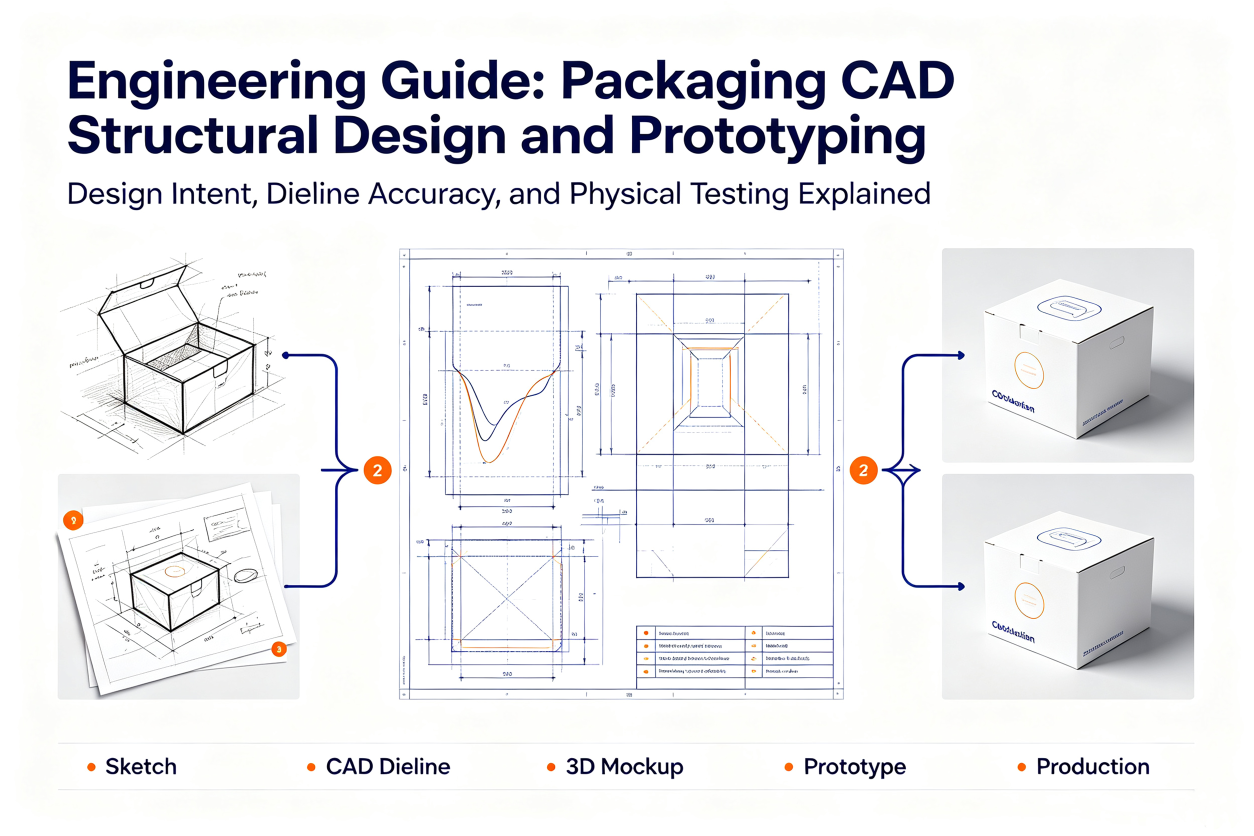
Eye-catching artwork requires a sound structural foundation. Professional packaging CAD structural design involves calculating folding mechanics, material stress points, paperboard grain orientation, and insert pocket tolerances to ensure your packaging is durable, functional, and easy to assemble.
At Gerun Packaging, our structural engineering department translates product concepts into precise digital vector dielines and physical structural prototypes.
[Product Physical 3D Scan/Measure] ➔ [ArtiosCAD Vector Dieline Build] ➔ [3D Virtual Folding Simulation] ➔ [CNC Plotter Knife Sample Cut]
Using digital calipers or 3D optical scans, engineers record precise product length, width, height, center of gravity, and fragile impact points to establish baseline internal dimensions.
Engineers map structural cut, crease, score, and perforation lines in specialized packaging software, taking paperboard thickness burn-rate allowances into account.
Before cutting physical board, packaging CAD structural design software folds the 2D vector dieline into an interactive 3D digital model to check for panel overlap, folding clearance, and latch engagement.
A physical sample is cut on a high-speed digital CNC plotter table. Oscillating drag knives cut outer edges while creasing wheels score fold lines on selected paperboard stock in minutes.
Q1: Why is paperboard grain direction critical in packaging CAD structural design?
Paper fibers align parallel to the manufacturing machine direction. Folding across the grain creates stiff structural box walls, while folding along the grain yields smooth crease folds without surface cracking.
Q2: What is “Board Crease Allowance” in dieline calculation?
When paperboard folds $180^\circ$, material thickness consumes internal volume. Structural CAD software automatically adds fraction-of-a-millimeter dimensional offsets based on board caliper thickness to ensure panels fold flush.
Q3: Can I receive a digital 3D vector dieline file from your CAD design team?
Yes. We export master structural dielines as 2D vector .AI (Adobe Illustrator) or .PDF files layered with exact cut, crease, and bleed dimensions, allowing your designers to place artwork accurately.
Q4: How does packaging CAD structural design prototyping prevent mass production errors?
Physical CAD prototypes let you test real-world product insertion, drop protection, and closure latching, catching fit or structural issues before cutting expensive mass production steel rule dies.
Q5: Can structural engineers design custom pop-up elements or intricate unboxing mechanics?
Yes. Structural engineers develop custom auto-locking bases, multi-tier sliding drawers, pop-up presentation platforms, and intricate geometric openings that elevate the unboxing experience.
Tel:+86 13723475723
Add:building 10, zone 14th, taoyuanju, xixiang street, Bao'an district, Shenzhen, 518126, China
Connect us by scan whatsApp

CUSTOM PACKAGING SUPPLIER FOR COSMETIC, GIFT, FOOD AND SHIPPING | 2026 COPYRIGHT BY GERUN PACKAGING